

HYDRAULIC DESIGN OF CULVERTS
As development of roads in India is taking place rapidly, cross drainage works have become an essential part of road construction.
Inadequate drainage invariably results in reduction of life span of a road.
Drainage costs (including culverts) are only 4% to 5% of the total project cost.

Some Important IRC Codes
- IRC:SP:42 (2015) – Guidelines for design of road drainage
- IRC:SP:13 (2014) – Design of Small bridges & culverts
- IRC:SP:50 (2015) – Urban road drainage
- IRC:SP:48 (1998) – Hill road drainage
PLANNING & DATA COLLECTION
- Planning of Culverts for Effective Road Drainage
- Location – New Projects / Up-gradation
- Types, Size and Spacing
- Data Collection
- Inventory
- Maintenance
HYDROLOGICAL DESIGN
Estimation of Design Peak Flood by:
(a) Rational Formula
Pm = Σ(Pi Ai) / ΣAi (i=1,2,3...)
Ic = (F/T) [(T+1) / (tc +1)]
tc = [0.88(L³/∆H)]0.385
tc = t1 + t2 + t3 + …
(b) SCS Method of Determining Peak Flood
Where:
Q = Accumulated run-off in mm
P = Accumulated rainfall in mm
Ia = Initial abstraction prior to run-off in mm
S = Potential maximum retention in mm
Procedure for estimation of Q is given in IRC:SP:42 (2015)
Return Period

Rainfall Analysis – Intensity-Duration-Frequency
| Type of Structure | Return Period | Frequency Factor |
|---|---|---|
| Drains | 10 yrs | 1.0 |
| Culverts | 25 yrs | 1.10 |
| Minor Bridges | 50 yrs | 1.20 |
| Major Bridges | 100 yrs | 1.25 |
Full Flow & Part Flow
Inlet & Outlet Control
Q = Co Ao (2gHW)1/2 – For Inlet Control (part flow)
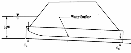
Typical Inlet Control Type Culvert with Orifice Type Flow at Entry
Outlet Control – Full Flow
H = total head loss at entry, exit and friction in m = He + Hf + Ho
= (Ke + Kf + 1) V²/2g or V = √[(2g H)/(1+Ke+Kf)] – Supported Flow
V = √[(2g H)/(Ke+Kf)] – Unsupported Flow

Typical Outlet Control Type Culvert with Supported Flow at Exit
- Size Governed by (i) Afflux (ii) Submergence u/s
- D/s Velocity / Energy Dissipation
- Debris / Annual Maintenance
- Improved Design where bottom is below Ground
- Inlet and Outlet Transitions
- Use of Software e.g. Culvert Master by Haestad
For Hydraulic Characteristics of Circular section click here → Link
My Suggestion
After observing various culvert cases, in which road gets over topped, due to insufficient discharge through pipe or due to blockage. In case of pipe culverts % obstruction is much more as compared wider openings of slab drains hence water gets stored (I don't think afflux word be appropriate in this case) then flood level rises on upstream side and road gets overtopped, to avoid such condition there must be free board between RTL and the maximum possible flood level on upstream side of the culvert. This will cause unnecessary leave increase in height of head wall but there is no need to increase the height of head wall as it can act as a toe wall for the slope of embankment, as shown in below drawing, help in achieving economy in construction as well as reducing maintenance cost for future.


0 Comments
If you have any doubts, suggestions , corrections etc. let me know