

Truss Analysis by Graphical Method

Logic: Force can be represented by Length, Direction and position of a straight line.
- Length ⇒ Amount
- Direction ⇒ Angle
- Position ⇒ Structural arrangement
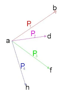
Representation of a Force
Force is completely determined when it is known in amount, in direction, and in point of application. Any force may be represented by a length, direction, and position of a straight line.
The length of the line is fixed by the relation between the amount of the given force and a pre-arranged unit of force. If the unit of force be taken as one Newton, a line of 3 meters long represents a force of 3 Newton. The graphical representation of a force may be designated by marking the line representing the force with the letter P followed in some instances by a subscript.

Extremity of the line may be indicated by a letter and the force referred to by means of these letters.

The direction of the force may be given where necessary by an arrow on the line representing the force. In the second method of designation given above, the order of the letters given in referring to a force indicates its direction — that is, in Figure 1B, referring to the upper force as ab indicates that it acts from "a" towards "b" while reference to the lower force as "ca" indicates that it acts from "c" towards "a". A diagram such as Figure 1 (a or b) which shows the analytical relation of the forces acting, their positions, directions and amounts is known as a "force diagram".
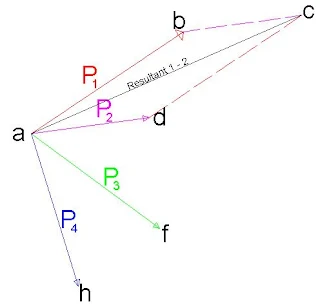
Composition and Resolution of Forces
In Figure 2, P1 and P2 represent two forces in the same plane acting at a point a. The amount of the resultant of the two forces is given by the length of the diagonal of the parallelogram "abcd" constructed upon the two given forces as sides. A single force applied at point a acting in the direction of point b of an amount represented by the length of the line ab will replace P1 and P2 in so far as accomplishing work is concerned. A force of the same amount but acting in the opposite direction will hold the forces P1 and P2 in equilibrium.
The Force Triangle

Reference to Figure 2 shows that, in order to determine the amount and the direction of the resultant of P1 and P2, it is not necessary to construct the complete parallelogram "abcd". From "c" of the force P1 a line "cb" is drawn parallel and equal to P2. The triangle "acb" is called the "force triangle" and represents graphically the relation between the forces P1, P2 and "ab".
The Force Polygon


Application of the Force Polygon

The Equilibrium Polygon

Resultant of Parallel Forces

Solving Roof Truss Using Above Methods


0 Comments
If you have any doubts, suggestions , corrections etc. let me know